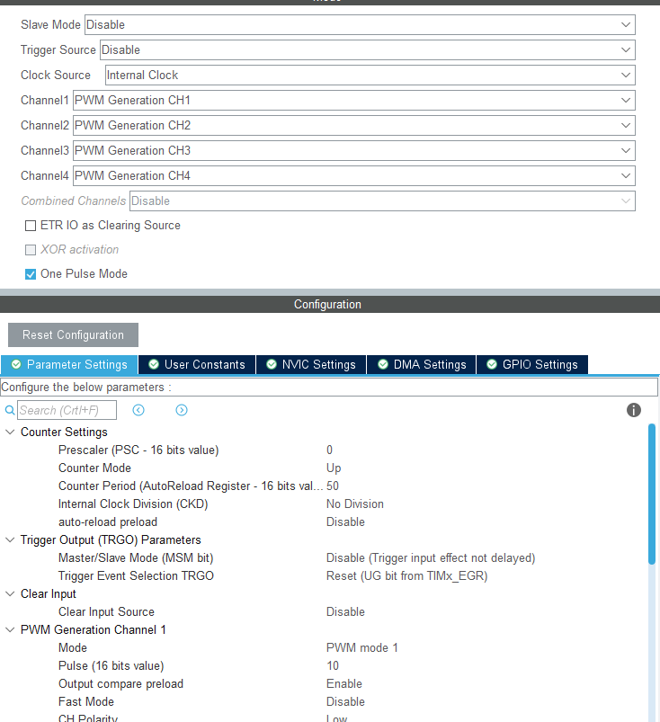
我认为你的使用有误,单脉冲模式是这样的
[C] 纯文本查看 复制代码 - The external signal is connected to TIM4_CH2 pin (PB.07),
and a rising edge on this input is used to trigger the Timer.
- The One Pulse signal is output on TIM4_CH1 (PB.06).
The delay value is fixed to:
- Delay = CCR1/TIM4 counter clock
= 16383 / 20000000 = 0,00081915[sec]
The pulse value is fixed to :
- Pulse value = (TIM_Period - TIM_Pulse)/TIM4 counter clock
= (65535 - 16383) / 20000000 =0,0024576 [sec]
The one pulse waveform can be displayed using an oscilloscope and it looks
like this.
LED3 is ON when there are an error.
___
| |
CH2 _________________________| |__________________________________________
___________________________
| |
CH1 ______________________________________| |_____
<---Delay----><------Pulse--------------->
| 


 发表于 2025-7-31 18:04:13


 发表于 2025-8-1 08:17:19
 楼主
楼主
